 Computer Lab
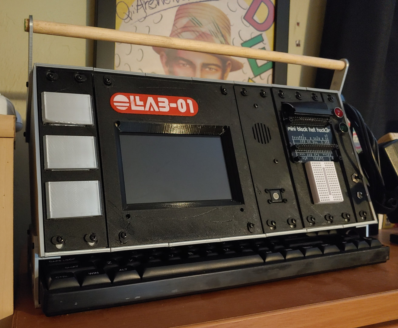
 Cyberdeck
Created: 2021-02-19, Last Update: 2021-03-24
A semi-portable Raspberry Pi Testbed, in the vein of Cyberdecks. It is built from modular parts and has extra space for swappable modules and prototyping. It was originally intended to be smaller, but accomodating the cables from the screen and the width of the tenkeyless keyboard, lead to it being rather large for this kind of device.
 Core Parts
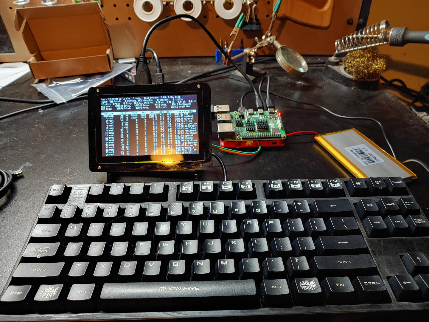
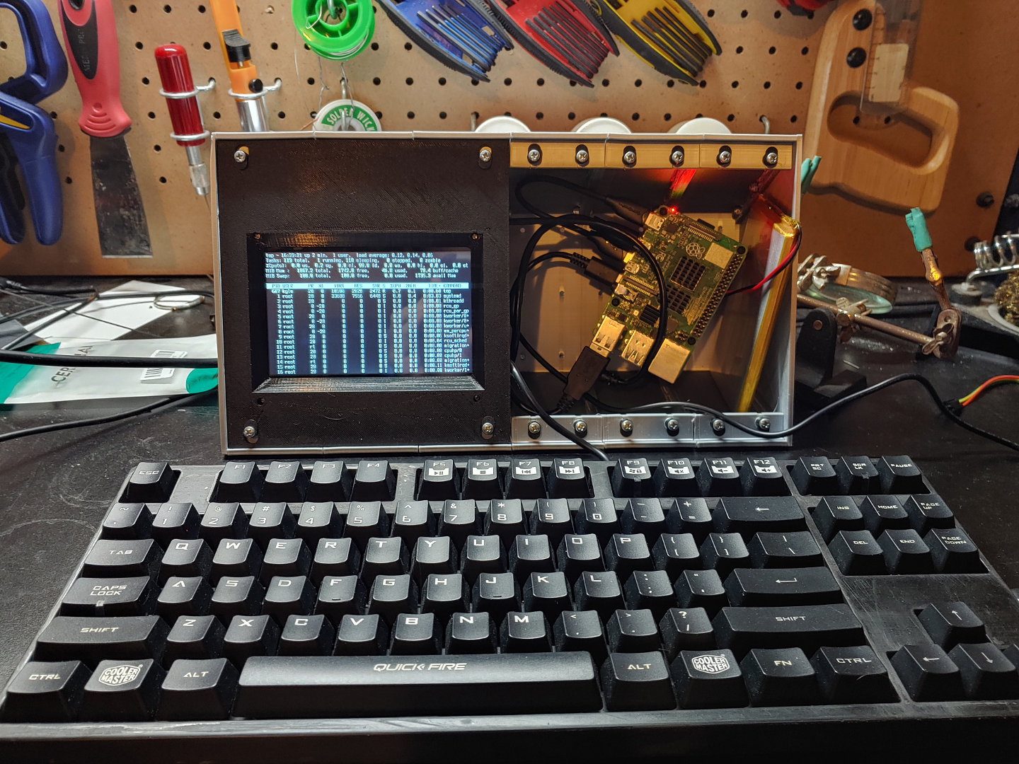
A Raspberry Pi 4B with 2GB RAM, a 5 inch screen and LiPO power board. The power board ends up not working out. The keyboard is an old Coolermaster with blue switches that had been retired from daily use due to it's finish wearing off. With some of the 3D prints being a bit rought, it seems to fit in. The screen was originally intended to go in some cheap FPV goggles from Walmart for a more portable concept. The goggles' optics weren't compatible with my eyes, nor the head mount with my glasses. So that idea was discarded, and this design built around the parts I had.
Construction
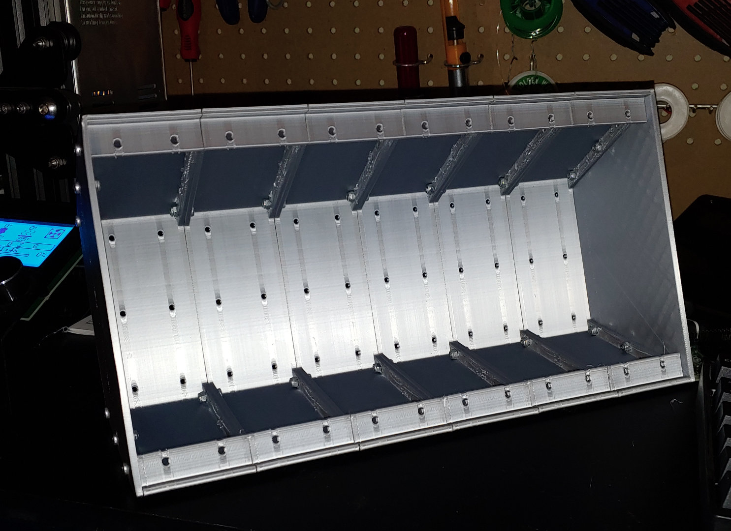
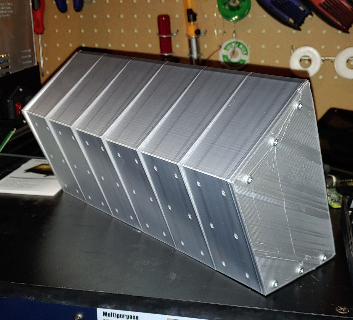
I started the design with a c-shaped back section that I could print repeatedly and bolt together. I then capped the ends with flat pieces bolted the same way. Once I had printed and bolted together a few, the design of the back part stayed the same. They print on the side, with one of the ribs overhanging. It gets a little stringy, but that gets hidden on the inside. The next problem was how to close the box if everything is held together with nuts.
I came up with a system of swiveling tabs to hold front panels in place. I made a big panel for the monitor. After a couple tweaks, it stayed the same for the rest of the project. I started test fitting the Pi, and realized that the masses of cables would be difficult to handle.
I did eventually cram all the cables in, partly by mounting the Pi close to the front of the case using stand-offs. I thought this was the moment of triumph, but the power board didn't work out. First, some soldering damaged the off-switch. So I wired my own power switch to the battery. I wanted an external switch anyway. However, now it would not run the screen off the battery. I should have expected this problem, because earlier tests had difficulty turning the screen on when booting from battery. I ignored that because I wanted to keep pushing forward on the case. After some thought, I decided to ditch the battery and power board altogether. For a testbed project, a high-capacity wall supply would be more flexible and reliable.
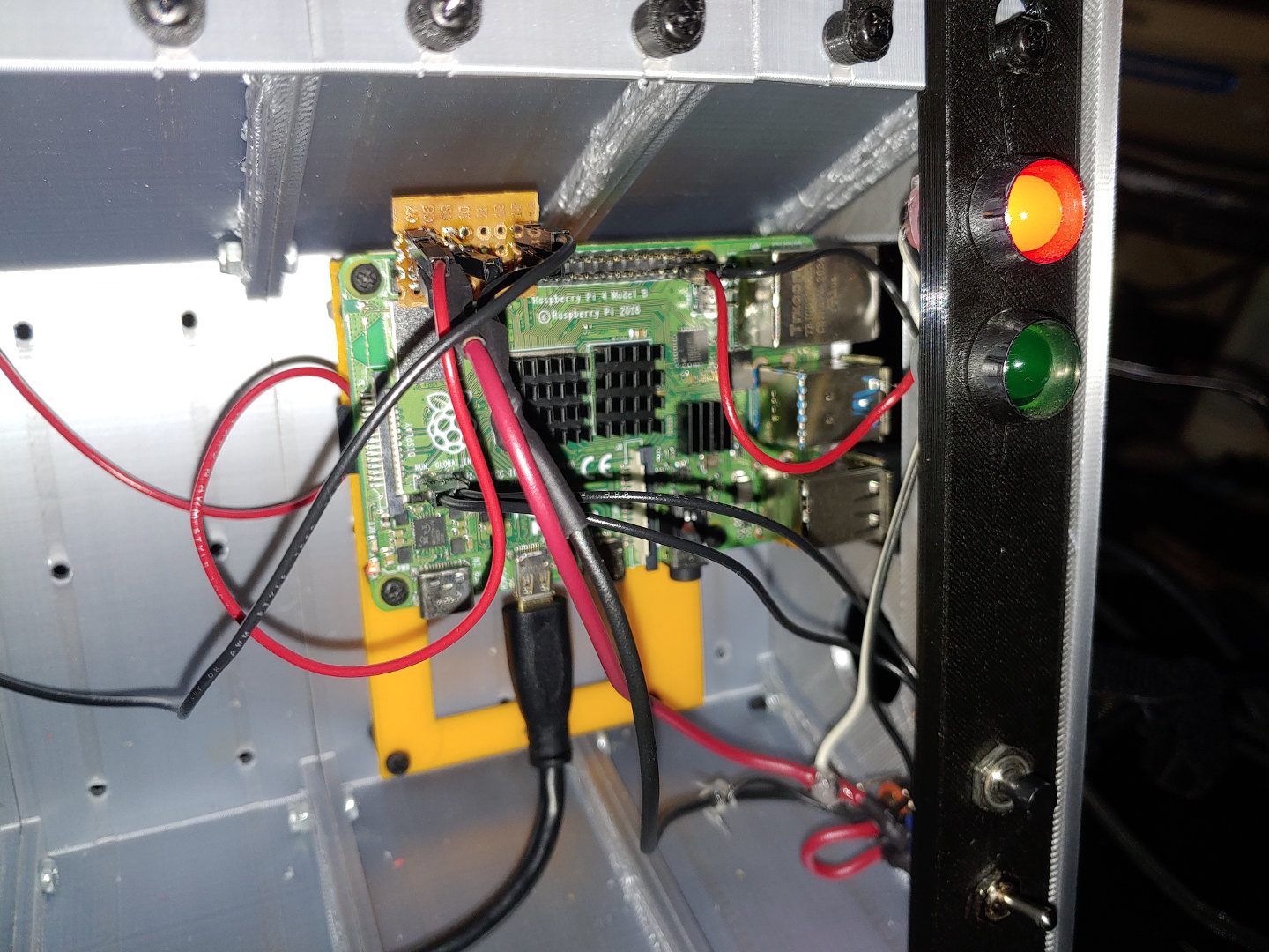
You can see here, the Pi mounting plate in orange, which was originally designed to have the battery tuck underneath, making it longer than is now needed. The power comes in from the socket on the right side, through the toggle switch. Dupont connectors connect the power wires to the Pi on two different pins each. A piece of perf board with headers duplicates the power connections from the Pi so that the power input and the screen can both be connected. The screen was originally connected via USB. I modified a cable to go to Dupont connectors, since I no longer had the extra USB ports of the power board. You can also see the LEDs and reset button here. The red LED is spliced into the power wires. The green LED is connected to GPIO via a Dupont connector, and I've set the Pi's configuration so that it becomes the activity light. The reset button is also connected via a Dupont connector, going directly to the "run" header to hard reset the Pi. Having the power connected with wires and dupont connectors freed up much of the space taken up by USB C cables in the previous design.
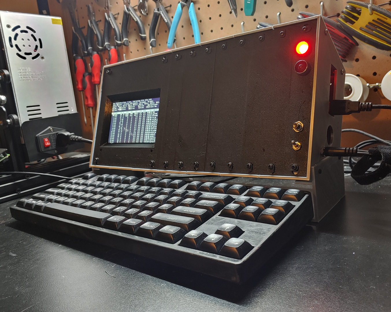
I moved the Pi to the far right side, exposing it's USB and Ethernet ports directly. This removed the rest of the cable bloat from the earlier iteration. I left a hole next to the ports, in case I want to route a usb cable back into the case later, such as for a pointing device. I swapped the keycaps for some nice 70's-terminal-esque ones that I had. ("Film Never Fades" by Tex, you may have seen them on this site before. Unlike on my current main keyboard, the spacebar fits fine here.)
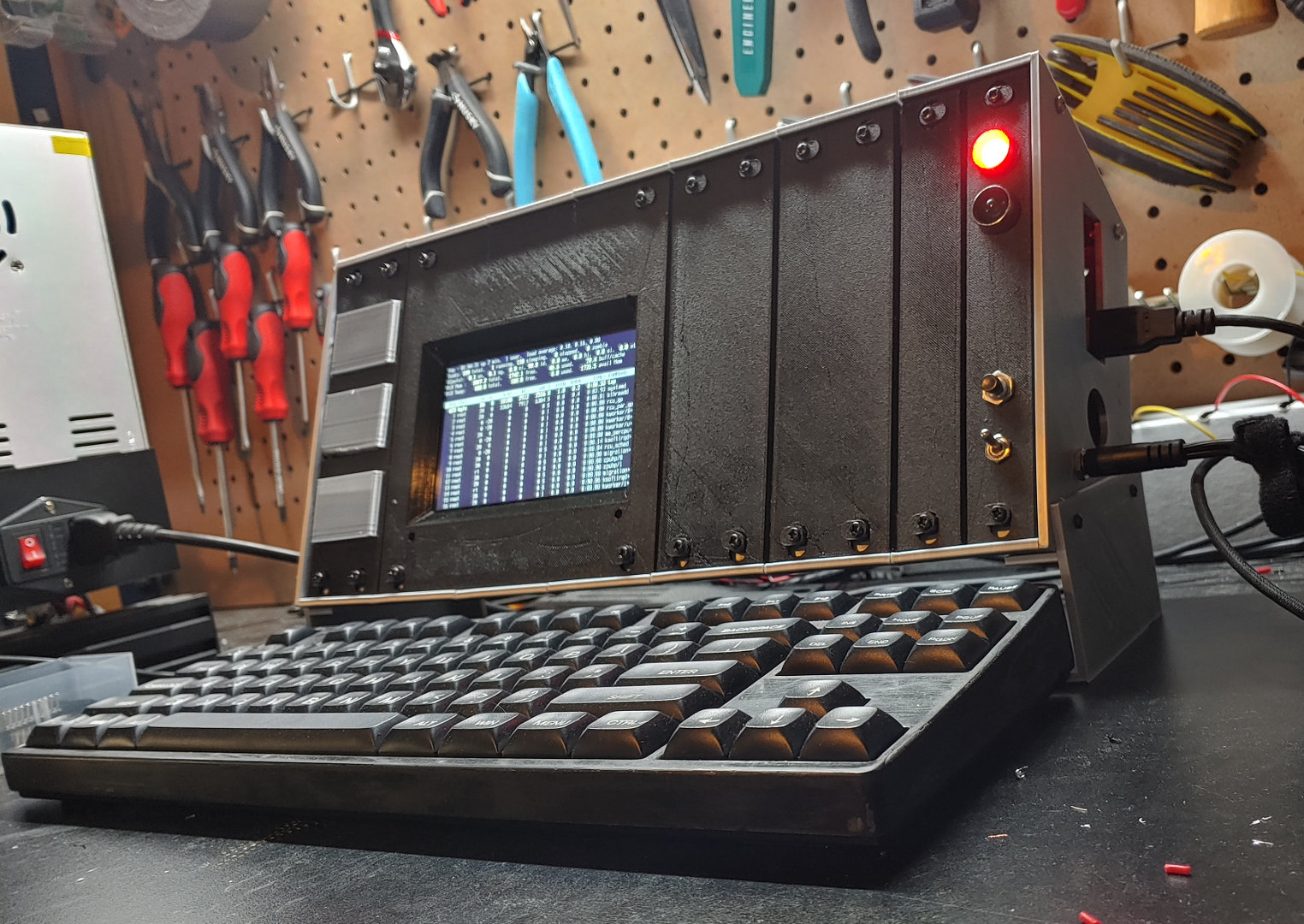
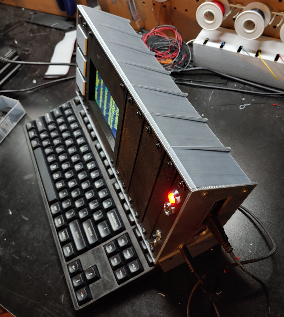
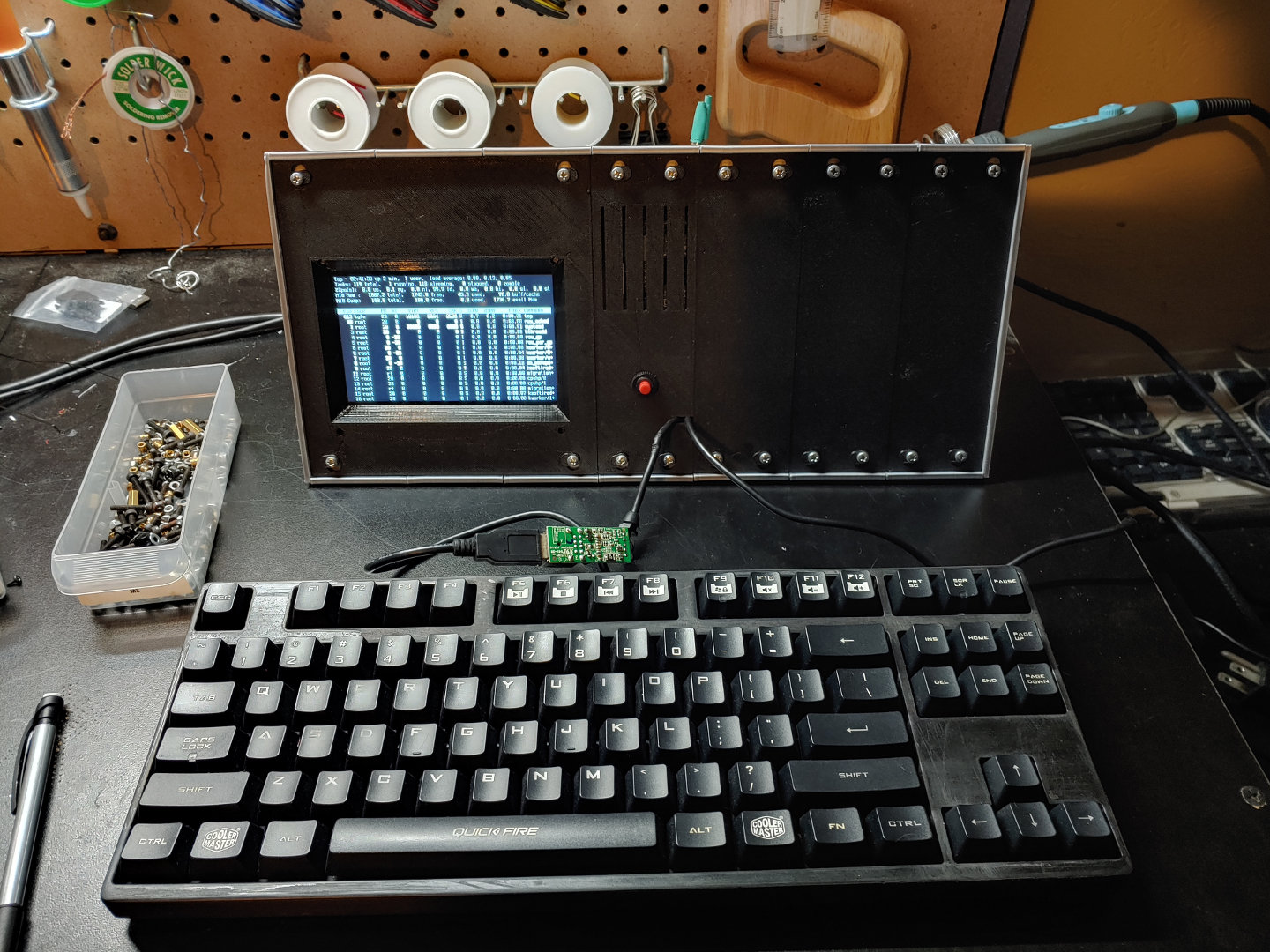
Around this time, I also added chamfers to the front panels to make them easier to add and remove. I added pieces to the sides so the keyboard could tuck in to save space. (Also theoretically for transport, if the plastic case doesn't come apart.) The silver panels on the left are drawers for parts storage. The middle one has a built-in Micro SD holder.
Post-Virtcon Updates
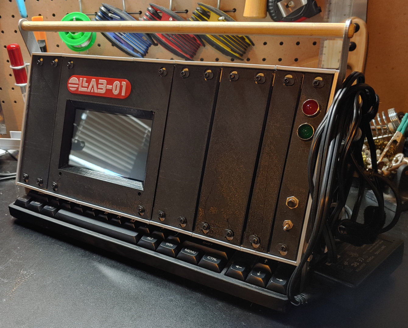
I added a wooden dowel as a carrying handle, and hooks on the side to wrap the power cord. The deck has been officially christened the "Lab-01" after a song by P-Model.
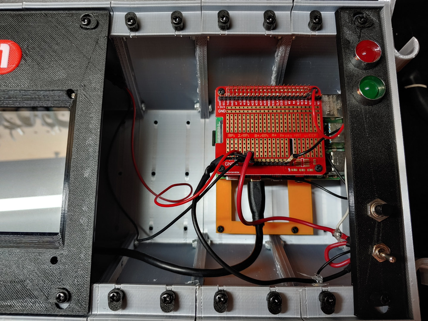
The perfboard for power distribution has been replaced by a proto-hat from Sparkfun with extra tall headers. In addition to being cleaner, this leaves room to connect other things to the GPIO.
Modules
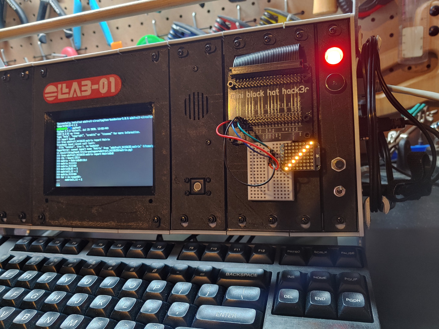
On the left is the WIMP module, with a mono amp and speaker, and a Pimoroni trackball. The amp is from Adafruit, the speaker is salvage from an old monitor. It sounds decent--a bit thin on bass, but probably better than a lot of laptop speakers. The trackball is functional, but not something I'd want to use often. The deck is mainly intended for command line use and coding, so it suffices. The trackball breakout is designed to connect to directly to the Pi, but for easier software compatibility, I've connected it via an Arduino Leonardo clone with a PCB that plugs into the USB port. (It's hidden behind the keyboard cable.)
On the right is the prototyping panel, with capacity for mini-hats and a labeled breakout courtesy of a Pimoroni Mini Black Hat Hack3r. I made some custom male to female jumpers to connect the GPIO to the breadboard. Originally I was considering having hats and breadboarding on separate swapable modules, using an Adafruit Pi T-Cobbler. However the T-Cobbler would have had to go on upside down and takes up most of the space on a half-size breadboard. (There's not enough room for a full-size breadboard on the deck.) I also considered putting female headers on the labeled breakout, but Pimoroni used very little solder, which makes it difficult to desolder and swap out the headers. In the end, the custom jumpers are easy to make from regular jumpers and a dupont crimper.

© 2026 Kyle Delaney | Site Map